BrickEngineer: LEGO Design

LEGO Engineering for LEGO NXT and Robot Enthusiasts

A Catalog of Omni-directional or Holonomic Wheels for LEGO Robots


I have been researching the possibilities for omni-directional or holonomic wheels for LEGO robots. An omni-directional or holonomic wheel is one that can roll not just backwards and forwards, but sideways as well.

New Rotocaster Omni-Directional Wheel

New Rotocaster Omni-Directional Wheel

While these are often used on robots with three wheels where all three rotate at different rates allowing the robot to go in any direction,

Three-Wheeled Omni-Wheel Prototype by Xander Soldaat at Bot Bench

Three-Wheeled Omni-Wheel Prototype by Xander Soldaat at Bot Bench (click on image to see more)


I am interested in using these on a rover that can employ differential steering smoothly without skidding.

There are several different options that one can consider. LEGO purists may consider making their own omni-directional wheel designs out of only official LEGO parts. Another option is to purchase manufactured omni-directional wheels. These come in two classes: those that are designed to be LEGO compatible, and those that are not LEGO compatible. In the latter case, one would have to construct some kind of coupling mechanism to enable the wheel to connect to LEGO parts.

Here are some of the options that I have found.

Omni-Directional Wheels Constructed from LEGO Parts

Omni-Directional LEGO Wheels by Xander at Bot Bench
These wheels use the LEGO pulley to get a six-fold symmetry. Each “wheel” uses 12 LEGO wheels. For archiving purposes, here are three pictures. Please visit Xander at Bot Bench for larger images and more details.

Omni-Directional LEGO Wheels by Xander Soldaat at Bot Bench

Omni-Directional LEGO Wheels by Xander Soldaat at Bot Bench

Omni-Directional LEGO Wheels by Xander Soldaat at Bot Bench

Details of Omni-Directional LEGO Wheels by Xander Soldaat at Bot Bench

Omni-Directional LEGO Wheels by Xander Soldaat at Bot Bench

Details of Omni-Directional LEGO Wheels by Xander Soldaat at Bot Bench

This amazing tank by Peer Kreuger also sports omni-directional wheels made from LEGO parts

LEGO Tank with LEGO Omni-Directional Wheels

LEGO Tank with LEGO Omni-Directional Wheels

The Omni Bot v2 by jason701802 also sports omni-directional wheels

Omni Bot v2 by jason701802

Omni Bot v2 by jason701802

LEGO-compatible Manufactured Omni-Directional Wheels

This LEGO-compatible wheel is made by the School of Robotics

School of Robotics Omni-Directional Wheels

School of Robotics Omni-Directional Wheels

Rotacaster makes a LEGO-compatible omni-directional wheel:

Rotacaster Robot Wheel (LEGO-compatible)

Rotacaster Robot Wheel (LEGO-compatible)

Rotacaster is also coming out with a new design

New Rotocaster Omni-Directional Wheel

New Rotocaster Omni-Directional Wheel

Rotacaster also produces several non-LEGO compatible designs.

Tetrix also makes LEGO-compatible Omni-Directional Wheels

Tetrix Omni-Directional Wheels

Tetrix Omni-Directional Wheels

General Manufactured Omni-Directional Wheels

Mecanum Omni-Wheel Designed by Bengt Ilon in 1973 at the Mecanum AB Company

Mecanum Wheel

Mecanum Wheel

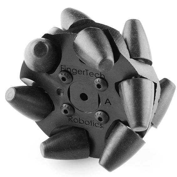
Mecanum Omni-Directional Wheel

Mecanum Omni-Directional Wheel

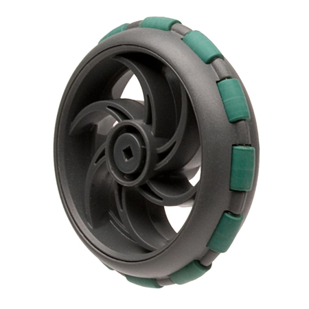
Vex Omni-Directional Wheel

Vex Omni-Directional Wheel

Vex Omni-Directional Wheel

Damon WH-01 Omni Directional Wheel (hexagon hole)
(Outer Diameter:60mm, Inner Diameter:11mm, Material: Nylon)

Damon WH-01 Omni-Directional Wheel

Damon WH-01 Omni-Directional Wheel

Kornylak Omni-Directional Wheel

Kornylak Omni-Directional Wheel

Kornylak Omni-Directional Wheel

Kornylak Transwheel

Kornylak Transwheel

Kornylak Transwheel

Kornylak Omni-Directional Wheel

Kornylak Omni-Directional Wheel

Kornylak Omni-Directional Wheel

Colorful LEGO Storage Ideas

In a previous post, Storing Your LEGO Collection, I discussed various options for storing one’s LEGO collection. Several of these options included tackle boxes since they can hold several utility boxes with adjustable partitions, while providing top bulk storage. I have found them to be quite useful in providing portable storage for small to medium LEGO collections.

Plano has come out with a new line of colorful tackle box designs geared for arts and crafts storage. These are the Creative Options
line of Storage Boxes and Organizers. The color scheme is a avocado green base with a purple lid and gold handles. These storage units are excellent for storing small LEGO collections while providing portability.

Here are some of the available models:

Grab N’ Go Rack System with 2 Deep #2-3630’s and 1 #2-3650 -Avocado Base/Purple Lid/Gold Handle

It comes with Two Deep #2-3630’s and One #2-3650 Prolatch Utility Boxes and Bulk Top Storage. It has dimensions: 13.1 x 9.9 x 13.6 inches

Multi-Craft Rack System

This includes three 2-3650 and two 3449 utility boxes and a compartmentalized top access storage on lid and large bulk storage area. Its dimensions are 17-3/4-Inch (Length) x 9-3/4-Inch (Width) by 11-Inch (Height).

Creative Options Grab & Go Storage Box/Organizer

This includes four #2-3500’s Prolatch Utility Boxes and Bulk Top Storage. ITs dimensions are 11-Inch (Length) by 7-1/4-Inch (Width) by 10-Inch (Height)

Be sure to check out some new ideas at:
New LEGO Storage Opportunities

Grown Man Builds LEGO Boba Fett Costume!

Geekologie posted an article about a man who made a wearable Boba Fett costume out of LEGOs. Mind you, its not a full costume. The helmet is most impressive, the rest are pieces of LEGO body armor that attach to his outfit.

LEGO Boba Fett Costume

LEGO Boba Fett Costume

LEGO Boba Fett Helmet

LEGO Boba Fett Helmet

Actually, I am a bit more impressed by the LEGO Darth Vader costume!
Who IS that masked man???

LEGO Darth Vader Costume

LEGO Darth Vader Costume

If only, it had lights that were controlled by the LEGO Mindstorms Brick, and a Breathing apparatus controlled by the LEGO pneumatic system!

Interface a Potentiometer to the NXT

NOTE: WE ARE NOT RESPONSIBLE FOR ANY DAMAGE YOU MAY DO TO YOUR NXT BRICK.
THIS EXERCISE PRESUMES SOME WORKING KNOWLEDGE OF ELECTRONICS.

In this exercise, I will walk you through interfacing a potentiometer (variable resistor) to the NXT brick.
You will need:
– A stripped NXT cable
– A potentiometer with a maximum resistance no more than $10 k\Omega$
– A small piece of wire
– An NXT Brick

This exercise is derived and expanded from a chapter in Extreme NXT by Gasperi, Hurbain and Hurbain.

THEORY

The NXT monitors the potential difference between the black and white wires with an Analog-to-Digital (A/D) converter. The A/D converter converts this potential difference to a RAW value between 0 and 1023 (10 bits accuracy). This RAW value is given by the ratio

(1) $RAW = \frac{RAW_{max}}{V_{max}} V_{R} = \frac{1023}{5} V_{R}$

where $RAW_{max}$ is the maximum RAW value of 1023, $V_{max} = 5V$ is the voltage used by the NXT A/D Converter, and $V_{R}$ is the voltage drop between the black and white wires.

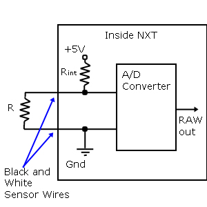
The circuit diagram looks like this:

NXT A/D Converter Schematic

I have a little $1k\Omega$ potentiometer that can turn over a range of about $0^{\circ}$ to $270^{\circ}$. Below is a diagram. The resistance between the leftmost and rightmost pins is the maximum resistance of $1k\Omega$. We will focus on the resistance between the leftmost and center pins, which varies based on the angle through which the potentiometer has been rotated. To keep things safe, we wire the center pin and rightmost pin together. This doesn’t affect the potential difference between the leftmost and center pins.

Potentiometer Wiring

I will assume that it is a linear potentiometer (a pretty good assumption), which means that the resistance at any given angle $A$ is given by

(2) $R = \frac{A}{A_{max}} R_{max} = \frac{A}{270} \times 1 k\Omega}$

where $A_{max}$ is the maximum angle of the potentiometer and $R_{max}$ is the $1k\Omega$ maximum resistance.

Equation (2) says that if the angle $A = 0^{\circ}$ then the resistance of the potentiometer $R_{max} = 0 \Omega$, and if the angle $A = 270^{\circ}$ then the resistance of the potentiometer is maximum $R_{max} = 1 k\Omega$.

Looking at the circuit diagram for the A/D converter, the potential drop across our potentiometer (represented by resistor $R$) is given by the typical voltage divider relation

(3) $V_R = \frac{R}{R+R_{int}} V_{max} = \frac{R}{R+10k\Omega} \times 5V$

We can now substitute (2) into (3) so that the voltage between the black and white wires is determined by the angle of the potentiometer rather than its resistance. Then we can substitute the result into (1) to get an equation for the RAW value

(4) $RAW = RAW_{max} \frac{A R_{max}}{A R_{max} + A_{max} R_{int}}$

with my particular values, this is

$RAW  = 1023 \frac{A \times 1 k\Omega}{(A \times 1 k\Omega) + (270 \times 10 k\Omega)}$

This formula will let us predict the NXT RAW value based on the angle of the potentiometer.

For my potentiometer, I find that a maximum angle of $270^{\circ}$ gives me a maximum value of 93. This is less than 7 bits of information, and each RAW value corresponds to $2.9^{\circ}$. If you want a nice angle detector, you will probably need a $10 k\Omega$ potentiometer!

TRY IT

1. Before beginning, you need to cut and strip one of the NXT cables so that you can interface with the wires directly. I have placed a layer of solder on mine, so they can be inserted into a breadboard for easy connecting.

2. Next connect the center and right pins of the potentiometer together with a wire

3. Plug the other end of the NXT cable into the NXT brick.

I wrote a simple NXT-G program to read the sensor and display the RAW value. Notice that the Touch Sensor actually reads the resistance between the wires. So we are just replacing the Touch Sensor with a potentiometer. We will use the raw number output of the Touch Sensor Block, which is represented by the 1010 0101 symbol. We then need to convert it to text so it can be displayed on the NXT LCD panel.

potentio-01.rbt Screenshot

You may download it here,
Potentio-01.rbt
or write your own.

When I try my potentiometer, I find that the RAW value goes from 0 to 95, pretty close to my predicted range of 0 to 93. So it works! Not bad considering I guessed that the potentiometer sweeps through and angle of $270^{\circ}$.


Determining the Angle of the Potentiometer

Now, let’s convert this RAW value to an angle.
In Extreme NXT, the authors worry about the fact that the resulting relationship is nonlinear with respect to the RAW value. As far as I can see, this isn’t a problem. We simply solve (4) above for the angle $A$ in terms of RAW. We can output the angle if we wish, but here I’ll take it a step further and demonstrate the resulting equation by controlling a motor so that it maintains an angle equal to the angle through which I have rotated the potentiometer.

I will leave out the algebra. Try it yourself. Solve (4) for angle A:

(5) $A = \frac{RAW A_{max} R_{int}}{R_{max} (RAW_{max} – RAW)}$

for my potentiometer, this is simply

$A = \frac{2700 RAW}{(1023 – RAW)}$

which is easy to code in NXT-G.
You can download my code here:
Potentio-03.rbt

The motor control is a bit crude, but it works well enough for the demonstration.
Check out the YouTube video to see it in action!

Enjoy!

Danny – NXT Matlab Bluetooth Router

Daniele Benedettelli introduces a MATLAB-based NXC Bluetooth Router. This router relies on connecting a master NXT Brick to a computer via USB. This master NXT Brick then can communicate messages to up to three additional slave NXT Bricks up to a distance of 10 meters from the master. This software would allow one to create small swarms of up to three LEGO robots, which is a nice starting point for investigating distributed robotic systems.

MATLAB NXT Bluetooth Router

MATLAB NXT Bluetooth Router

The system relies on the RWTH – MINDSTORMS NXT Toolbox, the NXT Fantom Library, and John Hansen’s enhanced firmware.  The brick software is written in Not eXactly C (NXC), which requires Brick CC 3.3.

Daniele Benedettelli also has a book published titled Creating Cool MINDSTORMS NXT Robots (Technology in Action)

Infrared-Ultrasonic Beacons for Localization

An article at NXTasy.org highlights a three-wheeled robot that moves in one dimension and detects signals from an external beacon that emits ultrasonic bursts.  The robot relies on a microcontroller that runs a Kalman filter to perform and maintain spatial localization.  The NXT software is implemented using the LabVIEW NXT toolkit

NXT Reciever with Kalman Filter

NXT Reciever with Kalman Filter

Details on the project can be found at http://www.convict.lu/htm/rob/ir_us.htm#Kalman

LEGO Rendering Tutorial: The Basics

This is the first in a series of installments that describe how to render high-quality 3D images of your LEGO creations.  You will need the following free software:

  • LDraw
  • MLCad
  • L3P
  • POV-Ray v3.6

which can be downloaded with the LDraw All In One Installer

In this tutorial, we will be aiming for a nice simple still image of three bricks.  In later tutorials, we will animate them.  That will require extra software to put a series of inages together to form a video or an animated gif.  I use Adobe ImageReady to make animated gifs, but there are cheaper solutions.

You can also download all the files we will create here
BE_render_tutorial_1.zip
and follow along.

STEP 1: Create an MLCad file of the scene to be rendered

Open MLCad and prepare to place a few LEGO pieces in the scene.

Step 1.1: Set up a 1×1 brick
On the upper left-hand side, click on Brick.
Drag the 1×1 brick into one of the three viewing panels.
With the brick selected click the RED color button to color it red.
Right-click on the brick and select Enter Pos. + Rot…
Use Position Values
should be checked
Set the X and Z values all to zero and Y to -100 (negative 100)

Step 1.2: Add a 2×4 brick
Following the steps above, find the 2×4 brick in the Brick list (+ will expand the list) and add it to the scene.  Set its color to YELLOW and its position to X=100, Y=-100,  Z=50.

Step 1.3: Add a 2×6 plate
Following the steps above, find the 2×6 plate in the Plate list (you will have to scroll down to the Plate tab) and add it to the scene.  Set its color to BLUE and its position to X=100, Y=-100,  Z=-100.

Be sure that these pieces are all at Y=-100.  The -y direction points upward and this will place them above the Y=0 plane.

Step 1.4: Save your work as part-zoo-1.ldr

The screenshot below shows what you should see at this point on your MLCad screen.

MLCad Screenshot

MLCad Screenshot


STEP 2: Create a POVRay file using L3PAO

Open LP3AO (L3P-Add-on) keeping in mind where you stored your MLCad files.  This figure shows you the basic L3PAO window.

L3PAO Screenshot

L3PAO Screenshot

Step 2.1: In the L3P-Add-on window set the Model File to point to your MLCad file.  To browse, you may need to click on the button labeled …

Step 2.2: In the L3P-Add-on window set the POV-Ray Output File to point to the folder where you want your POV-Ray file to go.  To browse, you may need to click on the button labeled …

Step 2.3: In the middle of the right-hand column is the Quality Level setting.  Set this to 2.  IF you select 3 it prints the LEGO logo on every stud.  If you want this, you may leave it.  But I prefer to remove them.

Step 2.4: At the bottom of the middle column is the Render upon Completion option.  This will launch POV-Ray automatically.  However, if you have problems with the automatic launch, turn this option off and load it manually.  In later tutorials, we will edit the POV-Ray file manually anyway.

Step: 2.5: To start L3PAdd-on click on the Run L3P button in the lower right.  This will create the POV-Ray part-zoo-1.pov file in the directory you specified, and possibly launch POV-Ray depending on the settings you used in Step 2.4 above.

STEP 3: Render the Image with POV-Ray

If you launched POV-Ray automatically, you will already have your image.  Here we assume that you will render it manually.

POV-Ray Screenshot

POV-Ray Screenshot

Step 3.1: Open POV-Ray and in the File Menu, use Open File to open the .pov file that was created by L3pAO.

Step 3.2: Once the file is open, you can simply press the Run button on the upper bar.  This will create a default image, which is a 640×480 .bmp bitmap image.  This is saved automatically in the same folder as your .pov file.  Here it is:

Part-Zoo-1 Default image

Part-Zoo-1 Default image

Note that the LEGO pieces are lifted up above the floor.  This is because we set their y-coordinates to be -100, which is above the floor at zero.  Remember that negative y is up.  We now look to change a few features of our render.

Step 3.3: If you click on the Ini button (to the left of Run above), you will go to a screen that enables you to change the size of the output image.  The Section field on the right has many options that include the resolution of the final image as well as whether Anti-Aliasing (AA) is used.  Try changing the resolution and look at the differences between anti-aliased images and non-anti-aliased images.

Note however, that the output images will always be saved in either .bmp or .png format.  You will have to use another program to convert them to other formats if you are interested.

Step 3.4: You can try playing with the commands in the .pov file.  POV-Ray acts like an editor and you can manually edit your files.  For example, there is a section near the bottom that reads:

// Floor:
object {
plane { y, 24 hollow }
texture {
pigment { color rgb <0.8,0.8,0.8> }
finish { ambient 0.4 diffuse 0.4 }
}
}

This code controls the floor of the image.  If you delete it completely, the floor will disappear as you can see here in this image:

Part-Zoo-1 with No Floor

Part-Zoo-1 with No Floor

Step 3.4: IF you don’t like the black background, look in the .pov file for the Background section:

// Background:
background { color rgb <0,0,0>}

Changing the rgb (red, green, and blue) colors to <0.7, 0.7, 1.0>:

// Background:
background { color rgb <0.7, 0.7, 1.0>}

Will give you an image with no floor and a light blue background:

Part-Zoo-1 with a blue blackground

Part-Zoo-1 with a blue blackground

We have explored making simple cad images in MLCad, generating a .pov file using L3PAO, and rendering a high-quality bitmap image using POV-Ray.   You should read through the .pov file and try to figure out what the different parts do.  You can change their values and re-render the image to see what impact your changes have.  Just remember that POV-Ray saves the changes on top of the original file,  so you may want to make a backup first.

Happy Rendering!

Content Protected Using Blog Protector By: PcDrome.